
Power Devices for Inverter Welding Machines
Fast recovery diodes and high voltage MOSFETs for inverter welding machines: high di/dt freewheeling, surge tolerance and thermal cycling at 100% duty.
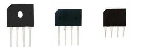
An inverter welding machine runs a high-frequency transformer at high current and high duty cycle, so its diodes must survive repeated high di/dt commutation rather than steady-state current. OCENME supplies 600–1200 V fast recovery diodes and 500–650 V MOSFETs for welding inverter stages, with IFSM, Trr and thermal cycling data stated per part number.
Scope of supply in this sector
This page covers inverter welders for MMA, TIG and MIG processes from 100 A to 500 A output, including the primary inverter stage and the secondary rectifier. It does not cover the welding control electronics or the wire feeder.
Requirements
| Output current | 100 A to 500 A welding current |
|---|---|
| Primary devices | 500–650 V MOSFET or IGBT, 30 A class and above |
| Secondary rectifier | 600–1200 V fast recovery diode, high IFSM |
| Duty cycle | 60% at rated output, 100% at reduced output |
| Switching frequency | 20–100 kHz depending on topology |
| Surge tolerance | Repeated short-circuit and arc-start surge |
| Ambient | 40 °C, dusty and conductive environment |
Materials we machine for this sector
- Epitaxial fast recovery die
- Silicon super junction and trench die
- GPP bridge die
- UL 94V-0 mould compound
Applicable standards
- IEC 60974-1 for arc welding power sources
- IEC 61000-3-2 harmonic limits
- EN 55011 / CISPR 11 for industrial EMI
- IP23 enclosure rating typical for site use (end product)
Typical parts
- 600 V to 1200 V fast recovery diodes, TO-247 and TO-3P, for secondary rectification
- 500–650 V MOSFETs, 20 A to 28 A, TO-220F and TO-247, for the primary inverter
- Bridge rectifiers 15 A to 50 A for the input stage
- Soft recovery diode variants where commutation ringing is the constraint
Quality risks specific to this sector
These are the failure modes we see most often in this industry. They are listed because knowing them before design review is cheaper than discovering them at first article.
- Secondary rectifier selected on average current while arc-start surge is several times higher
- Diode Trr quoted at 25 °C and used in a design that runs at 100 °C junction
- Conductive dust bridging terminals in a welder used on site, causing flashover
- Insufficient thermal cycling capability in a machine that heats and cools all day
Compliance and capability questions
Which diode survives a welding secondary rectifier?
A fast recovery epitaxial diode with a high IFSM and soft recovery, rated at 600 V or above, in TO-247 or TO-3P for thermal headroom. The critical number is not average current but surge: arc starting and short-circuit conditions push the diode to several times its rated current for milliseconds. Soft recovery also matters, because a snappy diode in a high di/dt loop produces overvoltage that kills the diode and the transformer insulation.
Why do welding machines need soft recovery diodes?
The commutation loop in a welder is physically long, so stray inductance is high. A diode that snaps off reverse current produces a voltage spike proportional to di/dt times that inductance, which can exceed the diode rating. Soft recovery spreads the transition and lowers the spike — it is a circuit-level fix that no snubber fully replaces.
Can MOSFETs replace IGBTs in a welding inverter?
For lower-power machines and higher switching frequencies, yes — MOSFETs avoid IGBT tail current and allow 100 kHz operation, which shrinks the transformer. Above roughly 200 A output, IGBTs usually win on conduction loss and ruggedness. We supply MOSFETs and diodes for the MOSFET-based designs; we do not make IGBT modules.
What documentation matters for a welder manufacturer?
IFSM and Trr with test conditions, thermal resistance, and a temperature cycling report. IEC 60974-1 type testing is done on the complete machine, so the component evidence feeds into that test rather than replacing it.
Industries we also supply
Power Supplies & Adapters
A switching power supply converts AC mains into a regulated DC output through a high-frequency converter, and its efficiency is decided by which devices switch and rectify. OCENME supplies the device set for adapters and open-frame supplies from 5 W to 300 W: 650 V super junction MOSFETs for the primary, 30–100 V MOSFETs for synchronous rectification, and bridge rectifiers from 1 A to 8 A for the input..
View sectorLED Drivers & Lighting Power
An LED driver is a current source, not a voltage source, so its devices are chosen for the current loop and the thermal environment rather than for output voltage alone. OCENME supplies 500–650 V MOSFETs, fast recovery diodes and bridge rectifiers for isolated flyback, non-isolated buck and PFC boost LED drivers from 5 W to 200 W..
View sectorTelecom & UPS Power
Telecom rectifiers and UPS systems run continuously at high ambient with a service life measured in a decade, so device selection is driven by derating margin and long-term stability rather than by peak efficiency. OCENME supplies 650 V super junction MOSFETs, SiC Schottky diodes and fast recovery diodes for rectifier PFC stages and UPS inverter legs, with HTRB and H3TRB reports per part number..
View sectorSolar & Energy Storage
A solar inverter or battery converter moves power in both directions at high frequency, so device choice is driven by switching loss and body-diode behaviour rather than by conduction loss alone. OCENME supplies 650 V and 800 V SiC MOSFETs, 650 V SiC Schottky diodes and 650 V super junction MOSFETs for boost stages and battery converters from 200 W to 10 kW..
View sectorSend the part number and the operating conditions
Tell us the voltage class, current, switching frequency and what the device is replacing. You will get a datasheet, a parameter comparison at matched conditions, and a quotation with MOQ and lead time.