
Silicon Carbide Schottky Barrier Diodes, 650 V / 20 A
650 V, 20 A SiC Schottky barrier diodes with 1.34 V forward drop, 130 A surge current and no reverse recovery, in TO-220AC, TO-220FAC and TO-247.
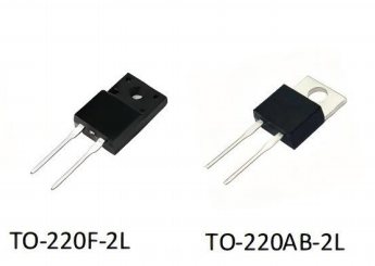
A SiC Schottky barrier diode is a majority-carrier rectifier with no minority-carrier reverse recovery, used where a silicon fast recovery diode would waste switching energy. OCENME supplies a 650 V, 20 A SiC Schottky family with 1.34 V forward drop, 130 A surge current and a 175 °C junction rating, in TO-220AC, TO-220FAC and TO-247 outlines.
Scope: what this product page covers
This page covers the 650 V / 20 A SiC Schottky family used in PFC boost stages, high-voltage output rectification, freewheeling in inverter legs and clamp duty. Silicon Schottky diodes below 200 V are a different family and are quoted from their own datasheet set.
Specifications
| Repetitive reverse voltage | 650 V (VRRM) |
|---|---|
| Average forward current | 20 A (IO at TC = 135 °C) |
| Surge current | 130 A (IFSM, 10 ms half sine) |
| Forward voltage | 1.34 V typical at rated current, 25 °C |
| Reverse recovery | No minority-carrier recovery; capacitive charge only |
| Junction temperature | 175 °C maximum |
| Temperature coefficient | Positive VF coefficient above a few amps, so parallel devices share current |
| Packages | TO-220AC (P), TO-220FAC (F), TO-247 (B) |
Materials
- Silicon carbide (4H-SiC) junction barrier Schottky die
- Copper lead frame with matte tin plating
- Moulding compound rated UL 94V-0
Manufacturing process
- Die incoming JBS die inspected and recorded against the foundry lot before dicing.
- Die attach and bonding Solder die attach with X-ray void sampling; clip or wire bonding depending on package.
- Moulding and cure Transfer moulding, post-mould cure, deflash and plating.
- Test VRRM, VF at rated current, IR at rated voltage and leakage at 175 °C tested at 100%.
- Surge and thermal sampling IFSM and thermal resistance verified on sampled units per lot and reported on request.
- Marking and packing Laser marking with polarity and lot code; tube packing with anti-static protection.
SiC Schottky Diodes in production
Typical applications
- Boost PFC diodes in continuous and critical conduction mode
- Freewheeling diodes in SiC and silicon IGBT inverter legs
- Output rectification in high voltage LLC and phase-shifted bridges
- Snubber and clamp duty in high-frequency switching cells
- Solar inverter boost stages
Quality and documentation
- Zero reverse recovery is a die property, verified by Qrr characterisation per die lot
- 100% test of forward voltage and reverse leakage at rated voltage
- 175 °C leakage test on sampled units, because SiC Schottky leakage rises steeply with temperature
- H3TRB and temperature cycling reports available per lot
- Polarity marking verified at outgoing inspection
What we do not do
A SiC Schottky is a unipolar device and is not a drop-in replacement for a silicon PN diode in every circuit: forward drop is higher at low current, and reverse leakage at 175 °C is orders of magnitude above a silicon diode. If your design depends on low standby leakage, this is the wrong part. We do not list 1200 V SiC diodes in the current set and do not claim automotive qualification for them.
Technical questions
Is a SiC Schottky diode a true zero-recovery device?
It has no minority-carrier reverse recovery, so Qrr is effectively zero. What remains is capacitive charge from the junction, which must still be supplied at every switching transition. That charge is why a SiC diode reduces but does not eliminate turn-on loss in the opposing switch.
Why does my SiC diode run hotter than the silicon diode it replaced?
Two reasons: forward drop at low current is higher than a silicon PN diode, and package thermal resistance is unchanged, so the same current dissipates more heat at light load. At high frequency the switching saving dominates and the SiC part runs cooler overall; below about 20 kHz the benefit can disappear entirely.
Can I parallel SiC Schottky diodes?
Yes, and more safely than silicon PN diodes, because VF has a positive temperature coefficient above a few amps — the hotter device takes less current. Below that crossover the coefficient is slightly negative, so parallel devices should come from the same lot and share a heatsink.
What surge current can the 20 A part take?
130 A for a 10 ms half sine at the stated starting junction temperature. That is a non-repetitive rating; repetitive surge, such as inrush into a capacitor bank, needs a thermal calculation with your repetition rate rather than a comparison against the IFSM number.
Adjacent products and capabilities
High Voltage & Super Junction MOSFETs
A high voltage MOSFET is an N-channel switch rated between 400 V and 800 V, used in offline power supplies where the drain sees rectified mains plus leakage-inductance ringing. OCENME supplies 500 V to 700 V planar MOSFETs and 650 V super junction MOSFETs from 150 mΩ, at continuous drain currents of 7 A to 28 A, in TO-220F, TO-262F, TO-263 and TO-252 packages..
View productSiC MOSFETs
A silicon carbide MOSFET is a wide-bandgap switch that replaces a silicon super junction device at the same voltage while removing most of the body-diode reverse recovery loss. OCENME supplies 650 V and 800 V SiC MOSFETs from 11 A to 20 A in TO-252 and TO-220F, with a 175 °C junction rating, for PFC stages, LLC converters and chargers running above 30 kHz..
View productFast Recovery Diodes
A fast recovery diode is a PN rectifier engineered for short reverse recovery, so it can freewheel in a switching converter without dominating turn-on loss in the opposing switch. OCENME supplies fast recovery diodes from 200 V to 1500 V in TO-220, TO-247, TO-3P, TO-252 and TO-263 packages, with Trr and IFSM stated per ordering code in the datasheet..
View productQuality & Inspection
CMM inspection to ±0.002 mm, FAI reports and PPAP documentation for every order.
Inspection capabilitySend the part number and the operating conditions
Tell us the voltage class, current, switching frequency and what the device is replacing. You will get a datasheet, a parameter comparison at matched conditions, and a quotation with MOQ and lead time.